Motorised Valve Wiring Diagram
Motorised valve (motorised valves) electrically controlled flow in heating and hot water pipes. If not, the structure won't function as it ought to be.
From the second column, identify the power requirement of.

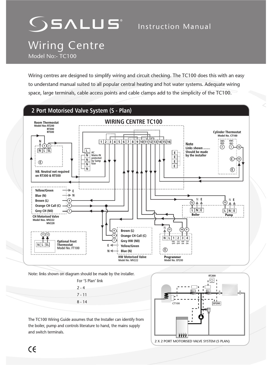
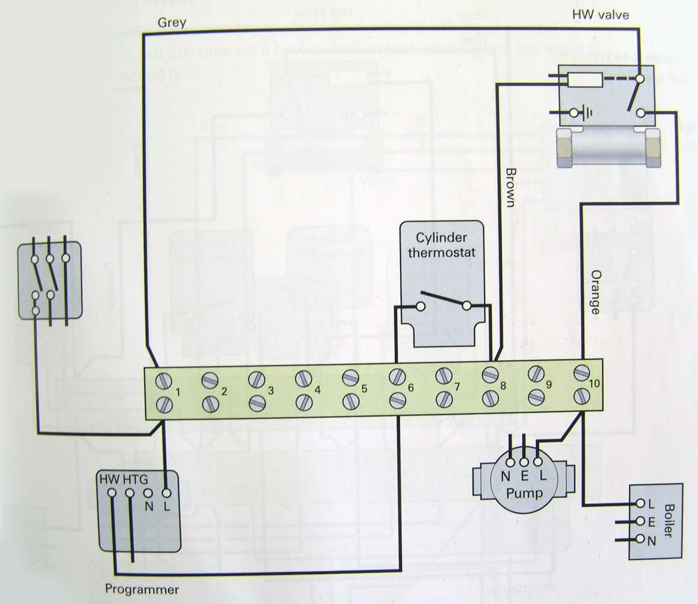
Motorised valve wiring diagram. If using the v4043h1080 (1 bsp) or v4043h1106 (28mm), the white wire must be electrically isolated. Wiring diagram of s plan central heating system typical motorised actuator valves: It includes instructions and diagrams for various varieties of wiring strategies as well as other products like lights, home windows, and so on.
Each part should be placed and linked to different parts in specific way. We are happy to help you solve the problem. Neutral (blue), earth (yellow and green), hot water off (grey), central heating on (white) and switched live out (orange).
If you have any demand for electric ball valve, electric butterfly valve or electric actuator, please contact. Motor operated valve wiring diagram source: For special wiring diagrams or applications, contact honeywell.
The mid position valve is supplied with 30 of cable connections motorised valve. Grey = permanent live to switch. The motorised valves are supplied fitted with a one metre length of heat resistant cable.
Fitting the valve body to the pipework 2.1 compression connection fit the valve body using the nuts and olives provided. Contains all the essential wiring diagrams across our range of heating controls. All about 2 port valves central heating and wiring!
The open vent and cold feed must not be isolated. Honeywell home v4043 motorized zone a motorised valve user s manual manualzz 2 port 5 wire application heating system buzzing sound from v4043h 22mm underfloor y plan diynot forums central tower two faults free wiring colours 40003916 001 powerhead for valves how does an work with. Our wiring diagrams section details a selection of key wiring diagrams focused around typical sundial s and y plans.
Orange = switch live output from switch. I'll show you how easy they are to wire on a heating system by ignoring the neutral and earth wires until. If using the v4043h1080 (1 bsp) or v4043h1106 (28mm), the white wire must be electrically isolated.
We also offer a two wire auto return valve. A switch (having contact separation of at least 3mm in all poles) must be incorporated in the fixed wiring as a means of disconnecting the mains supply. Honeywell v8043f1036 wiring diagram honeywell v8043f1036 powerhead pertaining to honeywell motorised valve wiring diagram image size 507 x 348 px and to view image details please click the image.
Gearboxes & valve accessories instrumentation & control pneumatic valves & manifolds. Ill show you how easy they are to wire on a heating system by ignoring the neutral and earth wires until. By control (wiring) by control (wiring) we have motorized ball valves available with 4 distinct wiring types.
Brown = live to motor. Motor operated valve wiring diagram can be a variety of can be 2 lines 3 lines 4 lines can also be connected with a feedback signal line 2 lines can also be with ground wire. Wiring diagram a drawing showing the various electrical.
Below is the wiring diagram for a v4043 motorised valve: Valve positioning install the valve so the actuator head is not below the horizontal level of the pipework. The flow must be in the direction of the arrow.
These can be used in conjunction with a dpdt switch, as simply switching the polarity reverses the action of the actuator. The simplest model is the 2 wire reverse polarity. Ensure that valve heads have free air movementaround them.
By andy blackwelloct 18 20214 mins to read. Any problem with wiring about covna valve, feel free to let us know. Honeywell home powerhead for v4043h valves.
('s'plan only.) the wiring diagram above shows relevant connections to a honeywell junction box (part no. The heating system must be appropriately fused for attached appliances. Click the icon or the document title to download the pdf.
In this article, we will share 8 options of wiring diagram of the covna electric ball valve and electric butterfly valve.
Honeywell Motorized Zone Valve Wiring Diagram Wiring Diagram

Honeywell Motorised Valve Wiring Diagram For Gif 1024 950 Beauteous S8610u In 1024x931 1024x931

Wiring Diagram For Danfoss Motorised Valve Wiring Diagram
Wiring Diagram For Danfoss Motorised Valve Wiring Diagram

Honeywell Motorised Valve Wiring Diagram Wiring Diagram And Schematic Diagram Images

How To Wire A Valve Switch Simple Wiring Diagram Heating Only. TwoPort Motorised Valve (Heating

Altech 3 Port Motorised Valve Wiring Diagram Wiring Diagram

Nest Wiring Diagram 3 Port Valve Nest Wiring Diagram

Honeywell Motorised Valve Wiring Diagram Wiring Diagram And Schematic Diagram Images

Sunvic 3 Way Valve Wiring Diagram Wiring Diagram

Motorised Valve Wiring Diagram

Danfoss 3 Port Motorised Valve Wiring Diagram Wiring Diagram
HVAC System 2 Way DN22 Female Motorized Control Valve

wiring diagram for 3 port motorised valve Wiring Diagram and Schematic

Wiring Diagram Honeywell Motorised Valve

Honeywell Motorised Valve Wiring Diagram Wiring Diagram And Schematic Diagram Images

wiring diagram for 3 port motorised valve Wiring Diagram and Schematic


